This blog post is brought to you by our manufacturer partner Marsh Industries.
If you have access to a suitable area of land, discharge from your septic tank or treatment plant to a properly designed and sized drainage field is the best environmental option as the treated effluent recharges groundwater, nutrients are retained in the soil, and nutrient loads on surface waters are reduced.
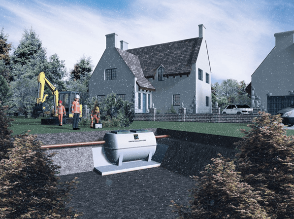
The most common form of drainage field is a subsurface percolation area comprising perforated infiltration pipes laid in shingle-filled trenches – normally within 1m of ground level to allow the micro-organisms in the soil to break down the organic matter, and at least 1.2m above the winter water table.
The drainage field has two principal purposes:
- To allow percolation of partially treated/treated effluent to ground at a controlled rate
- To allow further treatment of partially treated effluent before it reaches the groundwater level
Before you can dispose of effluent via a drainage field you first need to assess whether such a route is appropriate, i.e. you have a good depth of well drained, well-aerated soil away from watercourses, wells/boreholes, dwellings, and avoiding sloping sites and areas prone to waterlogging.
Trial hole and percolation test method
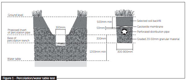
To calculate the exact area of land required for effective disposal an ‘assessment’ is required, usually by performing a percolation/water table test as outlined in BS6297 (Code of Practice for the Design and Installation of Drainage Fields for use in Wastewater Treatment) and the latest version of Building Regulations: H2.
A trial hole should be dug to determine the position of the standing groundwater table a minimum of 1m2 in area and 2m deep, or a minimum of 1.5m below the invert of the proposed drainage field pipework.
The groundwater table should not rise to within 1m of the invert level of the proposed effluent distribution pipes. If the test is carried out in summer, the likely winter groundwater levels should be considered.
A percolation test should then be carried out to assess the further suitability of the proposed area. A hole 300mm square should be excavated to a depth 300mm below the proposed invert level of the effluent distribution pipe. Where deep drains are necessary the hole should conform to this shape at the bottom, but may be enlarged above the 300mm level to enable safe excavation to be carried out.
Fill the 300mm square section of the hole to a depth of at least 300mm with water and allow it to seep away overnight.
Next day, refill the test section with water to a depth of at least 300mm and observe the time, in seconds, for the water to seep away from 75% full to 25% full level (i.e. a depth of 150mm). Divide this time by 150. The answer gives the average time in seconds (Vp) required for the water to drop 1mm.
The test should be carried out at least three times with at least two trial holes and the average figure from the tests should be taken. The test should not be carried out during abnormal weather conditions such as heavy rain, severe frost or drought. Drainage field disposal should only be used when percolation tests indicate average values of Vp of between 12 and 100. This minimum value ensures that untreated effluent cannot percolate too rapidly into groundwater. Where Vp is outside these limits effective treatment is unlikely to take place in a drainage field.
Drainage field construction
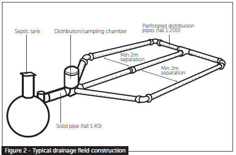
Drainage fields should be designed and constructed to ensure aerobic contact between the liquid effluent and the subsoil using perforated pipe laid in trenches:
- Pipes should be laid on a 300mm layer of clean shingle or broken stone (graded between 20mm and 50mm) at a minimum depth of 500mm and a uniform gradient not steeper than 1:200
- Trenches should be filled to a level 50mm above the pipe and covered with a layer of geotextile to prevent the entry of silt. The remainder of the trench can be filled with soil.
- Trenches should be from 300mm to 900mm wide with areas of undisturbed ground 2m wide being maintained between parallel trenches.
- An inspection chamber should be installed between the septic tank and the drainage field.
- Drainage fields should be set out as a continuous loop fed from the inspection chamber.
To calculate the floor area of the drainage field (At in m2), the following formulas should be used:
For septic tanks: At = p x Vp x 0.25
For treatment plants: At = p x Vp x 0.20
Where p is the number of persons served by the tank and Vp is the percolation value (secs/mm) obtained.
If it is not possible to discharge to a drainage field but you can discharge to a watercourse, coastal water or surface water sewer you should consider installing a package sewage treatment plant to treat sewage to a sufficient standard as to allow direct discharge to the receiving waters.
Tank sizing
The size of sewage treatment system you will require depends on the number of people that occupy the site and their activities, and it is at this stage you should re-contact Marsh.
Notes
Septic Tanks can only discharge to ground via a drainage field. Under the General Binding Rules 2020, discharge to a watercourse is not permitted.
Drainage fields are not permitted in Zone 1 groundwater protection zones.
Elevated drainage mounds can provide an alternative to drainage fields in certain circumstances, as they provide an aerated layer of soil where a conventional drainage field is inappropriate due to occasional waterlogging.
To learn more about Marsh Industries, login to The Build Chain and view their Virtual Exhibition!